Inventor: Mario Pasichinskyj
Primary Examiner: Kristine Peckman
Current U.S. Classification: 323/362; 323/330; 324/117.00R; 336/110; 505/879
International Classification: G05F 700
Patent number: 4904926
Filing date: Sep 14, 1988
Issue date: Feb 27, 1990
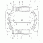
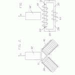
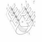
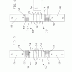
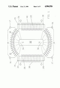
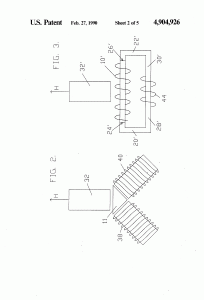
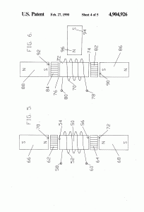
A magnetic motion electrical generator includes an electrical winding defining a magnetically conductive zone having bases at each end, the winding including elements for the removing of an induced current therefrom. The generator further includes two pole magnets, each having a first and a second pole, each first pole in magnetic communication with one base of the magnetically conductive zone. The generator further includes a third pole magnet, the third pole magnet oriented intermediately of the first poles of the two pole electromagnets and in magnetic communication with the electromagnets, the third pole magnet having a magnetic axis substantially transverse to an axis of the magnetically conductive zone, the third magnet having a pole nearest to the conductive zone and in magnetic attractive relationship to the first poles of the two pole electromagnets, in which the first poles thereof are like poles. Yet further included in the generator are elements for cyclically reversing the magnetic polarities of the electromagnets. Said reversing means, through a cyclical change in the magnetic polarities of the electromagnets, will cause the magnetic flux lines associated with the magnetic attractive relationship between the first poles of the electromagnets and the nearest pole of the third magnet to correspondingly reverse, causing a wiping effect across the magnetically conductive zone, as lines of magnetic flux swing between respective first poles of the two electromagnets, thereby inducing electron movement within the windings and thusly generating a flow of current within the winding.
Claims
- 1. An electrical generator, comprising:
- an electrical winding defining a magnetically conductive zone having bases at each end thereof, said winding including means for removing an induced current therefrom;
- two pole electromagnets, each having a first and a second pole, each first pole thereof in magnetic communication with one base of said magnetically conductive zone;
- a third pole magnet, said magnet comprising a permanent magnet, said third magnet oriented intermediately of said first poles of said two pole electromagnets and in magnetic communication with said electromagnets, said third pole magnet having a magnetic axis substantially transverse to an axis of said magnetically conductive zone, said third magnet having a pole thereof nearest to said zone and in magnetic attractive relationship to said first poles of said two pole electromagnets, in which said first poles thereof are like poles;
- control means for cyclically reversing the magnetic polarities of said electromagnets,
- whereby said control means, through said cyclical change in said magnetic polarities of said electromagnets, will cause magnetic flux lines associated with said attractive magnetic relationship between said first poles of said electromagnets and said nearest pole of said third magnet to correspondingly reverse, thereby causing a wiping effect across said magnetically conductive zone, as lines of magnetic flux swing between respective first poles of said two electromagnets, thereby inducing electron movement within said winding and thusly generating a flow of current within said winding.
- The electrical generators recited in claim 1 which said path of said wiping effect occurs along the same axis as a principal axis of said magnetically conductive zone.
- The generator as recited in claim 2 in which said electrical winding about said magnetically conductive zone comprises a helical winding.
- The generator as recited in claim 3 in which said magnetically conductive zone comprises a magnetic core.
- The generator as recited in claim 4 in which said core and windings comprise a superconductive material.
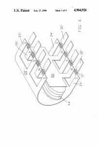
- The generator as recited in claim 2 in which said control means comprises flat spirally-wound elements, the plane of such flat spiral elements being transverse to said primary axis of said electromagnets.
- The generator as recited in claim 1 in which said control means comprises an electromagnetic path between said second ends of said electromagnets in which a polarity control signal is applied across said path.
- The electrical generator as recited in claim 7 in which said electrical winding about said magnetically conductive zone comprises a helical winding.
- The generator as recited in claim 8 in which said magnetically conductive zone comprises a magnetic core.
- The generator as recited in claim 8 in which said core and windings comprise a superconductive material.
- The generator as recited in claim 1 in which said control means comprises flat spirally wound elements, the plan of said flat spiral elements being transverse to the primary axis of said magnetic path of travel.

