Inventors: Alexander Thomas, Alexander Thomas
Current U.S. Classification: 310/305; 976/DIG.410
Patent number: 2876368
Filing date: Apr 6, 1953
Issue date: Mar 3, 1959
This invention relates generally to the generation of electrical energy and more particularly to unique methods of and means for utilizing the electrical energy of nuclear reactions to convert an electret from an electrostatic device to an electrodynamic current-producing device.
Heretofore, two general approaches have been made toward the direct utilization of the energy provided by certain nuclear reactions for the production of electric current, i. e., a source of battery power. One approach has been extensively investigated by Emest G. Under as exemplified by United States Patents 2,517,120; 2,527,945; 2,548,225; 2,555,143 and 2,598,925, which may be designated as the “direct” type of nuclear battery wherein current is produced by utilizing the directionality of a or 0 rays between the collecting electrodes. In essence, the battery comprises a radioactive source and one or more collector electrodes for collecting charged particle rays from the source, and means for applying the resultant unidirectional potential between the source and collector electrodes to a load. The efficiency of this type of battery is low at low voltages, and with presently known radioistopes can have reasonable efficiency only in the region between about 5 and 500 kilovolts. This being an unreasonable voltage for most applications where the relatively small currents generated can be used, batteries of this type have limited usefulness.
The other type of nuclear battery which has been investigated utilizes the field produced by the contact potential difference between two electrodes (formed of dissimilar metals) to collect the ionization produced by a or p radiations in a gas separating the electrodes. The maximum efficiency of this type of nuclear battery is the ratio of the contact potential difference (in volts) to twice the average energy (in electron volts) lost by the radiation per ion pair formed. This maximum efficiency, based upon known constants among the metallic elements, is about 5%. Moreover, since the maximum contact potential difference among the elements is only 3 volts, a large number of cells are required to obtain even several hundred volts of electromotive force in the gaseous type of nuclear battery.
The present invention contemplates the incorporation of a radioactive source in an electret to make the electret a current producing device instead of an inherently electrostatic device.
Among the objects of the invention are to provide an improved method and means for generating electrical energy in response to nuclear reactions. Another object is to provide an efficient method for utilizing the electrical energy in nuclear reactions to generate reasonable currents over a useable voltage range. An additional object of the invention is to provide a method for releasing the static energy of an electret to generate an electric current. A still further object of the invention is to provide a current source of relatively high voltage for its volume. Yet another object is to provide improved methods and means for utilizing the combined electrical energies of an electret and a nuclear reaction to produce an electrical current.
These and other objects of the invention will become apparent from the following detailed description when considered with the accompanying drawings wherein like reference characters are applied to like elements in the several figures and in which:
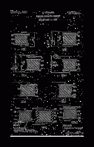
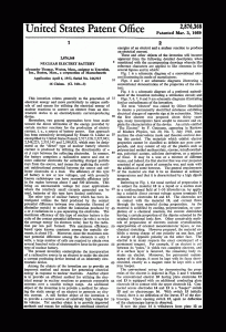
Fig. 1 is a schematic diagram of a conventional electret illustrating its mode of manufacture;
Figs. 2 and 3 are schematic diagrams illustrating a conventional demonstration of the properties of the electret; Fig. 4 is a schematic diagram of a preferred embodiment of the invention including a utilization circuit; and
Figs. 5, 6,7,8 and 9 are schematic diagrams illustrating further embodiments of the invention.
The term “electret” was coined by Oliver Heaviside to denote a permanently electrified substance exhibiting electrical charges of opposite sign at its extremities. Since the first electret was prepared about thirty years ago, many investigators have sought to measure and explain the characteristics of the device. An article entitled ‘The Electret” by F. Gutmann, appearing in Reviews of Modern Physics, vol. 20, No. 3, July 1948, sum- marizes the observations made and theories evolved during this period. The materials which exhibit electret properties cannot be classified as definite nor pure compounds, and may consist of any of the plastics such as polymerized methyl methacrylate, styrene, tetrafluorethylene, polyvinyl acetate, cellulose derivatives, or a mixture of these. It may be a wax or a mixture of different waxes, and indeed, the first electret that was ever prepared consisted of equal parts of carnauba wax and resin with the addition of some beeswax. The general requirements of the material are that it be an insulator at ordinary temperatures and that it is characterized by a high dipole moment.
Referring to Fig. 1, the usual method of preparation is to subject the material 10 in a liquid or a molten state to a unidirectional field of 1-30 kilovoIts/cm. by applying a suitable direct current voltage across terminals 11 connected to electrodes 12 and 13. The electrodes are in contact with the material 10, and current flows through the base material during preparation. As the material is solidified by cooling, polymerization, or completion of a chemical reaction, the current diminishes leaving a certain proportion of the dipoles oriented by the original directional ionic flow. Other conceivable methods of. preparation of electrets include crystallization, superposition of oriented monomoiecular layers, or mechanical stretching. However prepared, the material exhibits a strong charge of one polarity on one face, and a charge of opposite polarity on the other face. The electret is in many respects the exact counterpart of a permanent magnet. For example, if an electret is cut between its “poles,” it yields two complete electrets, and if a surface layer is removed, the remaining body remains an electret. Moreover, for permanent maintenance of its charge, it must be kept with its faces short- circuited, exactly as a magnet must be kept with a soft iron keeper.
The conventional set-up for demonstrating the properties of the electret is depicted in Figs. 2 and 3 wherein the conventional electret 10 having plate electrodes 12 and 13 is equipped with an additional conducting plate electrode 14 in contact with the upper electrode 12. Connected across electrodes 14 and 13 is a “keeper” switch 15 and an electroscope 16. With switch 15 initially closed, there is no deflection of the leaves 17 of the electroscope. Upon opening switch 15, again no deflection of the electroscope leaves is observed.

