Circuit design:
The main purpose is design a circuit for discharge a condensers bank for tap energy in the nuclear reaction performed in a pure carbon rod with the following dimensions:
Length = 60 millimeters
Diameter = 6 millimeters
Then, the volume of the carbon rod will be 1,7 cm3, value for consideration in the required energy level for the initial nuclear activation process inside of the carbon rod, at more volume more starting activation energy and more energy at the output , this is because the carbon rod used for you can be of different dimensions and may be no a pure carbon rod, if the rod is not pure the calculations can be approached as if it was pure, is best use an excess of energy than use a value down the minimal starting required This dimension values are the same used for Nikola Tesla in his electrical car builded in 1931, inspired from that are this dimensions used. Now for design of the other parameters we must know what
Resistance of the carbon rod = 0,18 Ohms
Voltage of the condenser bank used = 37 Volts DC
And so, we can see a peak of current in the condenser discharge of a maximal current of 37 / 0,18 = 206 Amperes , value for consideration in the choice of the power Fet can support that short pulses of current, the true value of the discharge current peak will be more because the parallel resistance added for the electrode reduce the initial resistance of the carbon rod.
For get the energy of the beta radiation o or high energy electrons I use a toroid wired of
the following way
Diameter = 6 mm
Number of turns = 300 , with wire of 0,5 mm of diameter
Polarization magnetic field = 135 gauss
The shape of the toroid and rod is shown in this photo:
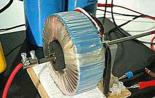
We can see in the background of the picture 2 condensers in parallel, 80000 microfarads each, the nucleus of the toroid is isolated in metallic paper for caution of radiation escape The volume of the carbon rod establishes the minimal energy for starting the nuclear reaction , value we can calculate, as I was a DC power source of 37 Volts that is the stating charging voltage of the condensers bank and the total capacity as before mentioned is 160000 microfarads.
The condensers bank I was using don’t was electrolytic, I use Mylar condensers, 2 condensers of 80000 micro Farads each, I suggest not use electrolytics, each condenser support until 50 V DC each, however we can work with others voltages and others capacity values, the formula for the energy stored in a condenser is

Where C is the capacity in Farads and V the load voltage , then we can see the more influence variable is the voltage V, that is say if we double the voltage the capacity for get a certain energy level will reduce 4 times, or if we use 10 times the initial voltage the capacity will reduce 100 times, and so if we use high voltage the capacity will reduce notably , the limit is in the voltage can drive the power transistor used , for that reason Tesla was using vacuum tubes because it support high voltages, and can be used as condensers or transistors, in this case we must keep the following proportion:

That is say, the energy stored in this condensers bank is about 109 Joules, and in the following we can see a table for voltage in load and capacity of the condenser bank and you can choice the best option according your resources
| Case | Capacity (micro farad) | Voltage ( Volts ) |
|---|---|---|
| 1 | 1521200 | 12 |
| 2 | 380300 | 24 |
| 3 | 87620 | 50 |
| 4 | 21920 | 100 |
| 5 | 9740 | 150 |
| 6 | 2280 | 311 |
| 7 | 760 | 540 |
For the case 5 is like connect a condensers bank to an electrical net of 110 VAC, the case 6 is for a net of 220 VAC, and the case 7 for the voltage between the lines or phases in a triphase system of 220 VAC for phase and 380 VAC between the lines.
If we call VOL to the volume of the carbon rod in cm3, he value of the condenser the value estimated for this table must be multiplied for the factor

For example if we connect in a 311 VDC system this device and the carbon rod volume was the half of the original, that is say , F = 0,5 and then the absolute value of the condensers will be 1140 micro farads
Circuit design:
In this case I was using a transformer of 24 VAC , 3 amperes with rectifier for get the 37 VDC output, I put a resistance in series of 10 Ohms, 1 watt, with the purpose of limit the charge current and don’t destroy the transformer as in this picture
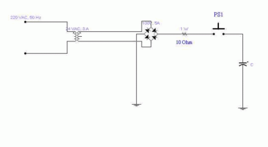
This circuit connected to the electrical net or other external source is for the PRECHARGE of the condenser, the idea is start the circuit with that charge and energy, the rectifier bridge used was of 100 VDC, 5 amperes, and so, for charge the condenser by pressing PS1 for a short time of seconds it get totally charged, in this case, with 5 seconds is right because the time constant here is about 2 seconds for the 0,16 microfarads used.
The power delivered in watts of our precharge source can be of ANY value, that is say, we can charge our condensers bank from a power source of MILIWATTS, I have used a power source here about 70 watts rms for the precharge, but is possible you can use a little battery AA of 1,5 V and a circuit for raise the voltage output, the time charge will be large, but you can see here miliwatts for input and kilowatts for output.
When the condenser is charged it is connected to the main circuit start the system as show in the following
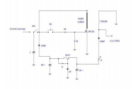
The translation for the figure is:
Al circuito de precarga = To the precharge circuit
Barra Carbón = Carbon rod
Toroide = Toroid transformer
A la carga = To the output load
The circuit show a pulser switch start the process, previous activation of the switch SW1 for disconnect the precharge circuit to this circuit of discharge with the Fet transistor, I use the Fet IRF3205 for the condenser discharge overdimensioned for sure the needed current pulse of 260 A and I have estimated an excess of 100 A, this transistor support pulses up to 390 Amperes, an adequate value for the 320 Amperes measured , the discharge carbon rod, the toroid and his polarization circuit generates the field current for the magnetic dipole alignment inside of the carbon rod and trap the electrons at the same time, the polarization circuit is powered from the same discharge condenser for get charged a secondary internal power source of 12 VDC.
The resistive trimmer of 1 Kilo Ohm is of 1 watt and of the wired type, for control and measurement the field current I do many tests with severals values of the field current until get the optimal output.
The output load is connected with a more diameter wire to the same output polarization of the toroid with a diode for stop a return of the output power to the polarization circuit.
Starting the system:
The components carbon rod – toroid – electrode must be enclosed in a box of good insulation using concrete or other material and let the output electrical terminals for sure caution for radiation escape is beta radiation in this case, is recommended use a radiation meter for the best health of the people work in this buildings.
The first discharge of the condenser through of the carbon rod we can see in the toroid the following wave form of voltage output.
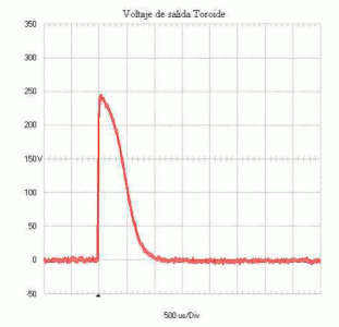
Voltaje salida toroide = Output voltaje in the toroid
The wave form was obtained using a portable digital oscilloscope with memory hold, a Fluke 123.
Of the same way, if there is not polarization current for the toroid the wave form for the voltage output in the toroid is as the following
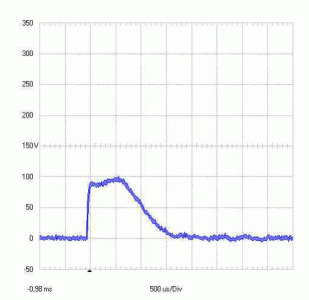
We can see the pulse is too large and of less amplitude.
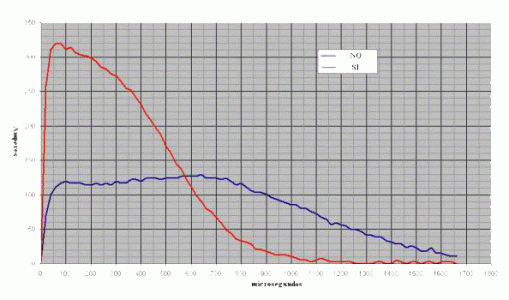
At the same time the current for the carbon rod is measured and there is a peak of 320 Amperes with the same wave form and pulse duration of 1660 microseconds with the toroid energized and that wave form of current we can see in the following.
microsegundos = microseconds
NO = Not , there is not polarization current for the toroid SI = Yes , there is polarization current for the toroid
The red curve show the discharge current for the carbon rod with the toroid energized, and the blue curve the same current but with the toroid without polarization current, the labels NO and SI is for show if there is or not current for the toroid.
We can explain the fact for the state not energized toroid where there is a current less than the theorist peak maximal estimated in the begin of 206 amperes for the series resistance of the contacts, wires used in series with the carbon rod, is notorious there is not the typical exponential discharge wave form of a condenser explained for the nuclear reaction process inside of the carbon rod and the electron excess sustain the current for a time. The current was measured with a current transformer by using a toroid wired with 1143 turns loaded with a resistance of 880 Ohms.
This configuration according to the turns ratio in the main toroid delivers a power output of 5488 watts rms with the polarized toroid as will be shown in the following.
In resume, for the meditions we see before, if we cancel the toroid polarization and we do the same meditions we see a short of the timing pulse to 1330 microseconds, the peak voltage reach up to 100 Volts, and the current in the rod is reduced to 130 amperes peak The current data obtained we can do a square power elevation and multiply by the resistance of the carbon rod and multiplied for the time and we get the energy calculation in the rod in both cases, the processed result is the following
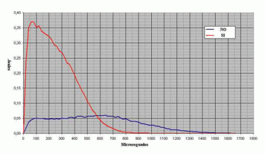
The energy scale is reduced in a factor of 100 for the digital signal processing , that is say, the real values of energy of the picture is multiply for 100 that graphic data, for example the peak of the stored energy in the carbon rod without polarization in the toroid is about 6 Joules and the peak with the polarized toroid is about 37 Joules.
For calculate the delivered power of this system we must work with average values, that is say if we calculate the average value for the energies and we do the division for the pulse width of each pulse we get the active power in the load in watts, the graphic data is processed in digital mode for integration and calculate the average value in each case and we have
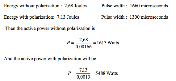
That is say, in the normal discharge of the condensers bank there is a power output of 1613 watts with the nuclear reaction without polarization in the toroid and there is not output power useful because the beta rays loose and there is not sucking of free electrons, but when there is polarization there is a power output 4 times the initial value, and there is energy gain and power gain, the power gain is about 3,4 but the energy gain is about.
2,66 when the toroid is polarized and there is an excess in the power output of 3875 watts and an excess of energy of 4,46 Joules , in other view, the power and energy needed in the time interval for the toroid polarization is too little for this values measured and calculated, this is not against the initial description about we can charge the condensers bank using miliwatts, here we see a charge process can be of miliwatts and a discharge process of kilowatts, it is not an inconsistence because the energy stored in the condensers can be discharged in short time but the charge process can be delivered in a time too much long.
All has been measured with the digital oscilloscope, that instrument can meter and hold in his memory wave forms of voltage and current such as the shown here, other digital process in that instrument as the energy graphic is acquired for the RS232 port of the instrument and the software used for sort and process the data. All this can be measured and tested easy in any laboratory with the carbon rod you can choice, notice the experimental results match with the initial calculations or deductions, the pulse duration is in the RC order, where R is the rod resistance and C de condensers bank capacity.
Now, this energy amplification factor of about 3,5 times , as always DON’T violates the energy conservation law because in the carbon rod there is an internal energy output and the sum of the energies before and after is always the same like an explosive when we start the explosion using a little activation energy, and this fact for more energy in the output than in the input make possible a feedback or closed loop operation or autopowered operation for stable output, however before of build the closed loop stage is recommended build the basical discharge pulse test for sure all is right.
If we want more power, more kilowatts in the output we must use more carbon mass , in this test I use only 1,7 cm3 of carbon volume, if we think there is 8 KW of useful power for each gram of carbon used the power levels we can get is too big.
For the closed loop operation in this case we must the condition than the power input requires 1613 watts then of the output power we must do that subtraction of power and we have 3875 watts of usable power , but before we must build the basical discharge circuit as here was shown for sure all works done, a practical method is the measurement of the voltage in the toroid output and adjusting the pulse width using the LM555 the closed loop operation go well, but before we must sure the discharge process is optimal.
Resume:
The discharge to the carbon rod without polarization in the toroid get the nuclear reaction in the internal structure of the rod, but as there is not alignment of the magnetic dipoles inside of the rod there is not a coherence in the electrons emissions for sum electrons to the electrical current in the carbon rod and there is not the necessary acceleration of the electrons inside of the carbon rod like the cathodic rays in a TV monitor , remember electrons inside of a conductor moves too slow and here we need a big speed added for the capacitor bank discharge and the polarization magnetic field of the toroid get an acceleration effect.
Testings and meditions shown here are for a first cycle of starting of the device, the closed loop operation is obvious, but here is not shown because is not practical, you will have a setup not equal to the used here, for that reason is than you build his discharge setup and get his parameters measurements for get the best values of feedback timings and the feedback power. The device is portable because one time is required for the start of the system and since the system is precharged it is portable and can start in any place and weather condition and any transportation conditions.
For finish, we can use not only solid plasma, discharges in gas tubes get the same results without magnetic polarization because there is a return of power to the initial starting discharge condensers bank, neon tubes is an option. More questions to the following emails [email protected] [email protected] See: http://jlnlabs.imars.com/vsg/vsg35.htm


