The Electron~Valve Converter
A Vacuum Tube with Filament Currents of 4400 amp. And Plate Voltage of 200,000 Volts
As our industrial civilization grows in complexity, power generated at a convenient location must be transmitted to more and more distant places. At the present stage of electrical development transmission lines extend over as much as 300 miles and the time is not very distant when centralized generation with concomitant large area distribution will become general practice in the electrical industry. These requirements will raise new and difficult problems, which the engineer will have to solve before long distance transmission becomes practicable.
Among the for most of these problems is one involving the voltage of transmission. At high voltages the air between conductors becomes ionized and corona losses result. This loss, over a large range of frequencies, is proportional to the frequency of the current transversing the line, and by making the frequency zero, that is, by using direct current, the corona loss may be made as small as ½ or ¼ of the loss at a frequency of 60 cycles per second.
Now long transmission systems require high transmission voltages and these in turn may cause serious corona losses (Fig. 1). It may therefore be of great advantage to transmit power in the form of direct rather than alternating current. However, alternating current machinery has become so prevalent that such current must be available at the receiving end of the transmission system. Further, great difficulty has been experienced in the pat with the generation of direct current at high voltages, the alternating current generators being very much better adapted, by virtue of higher insulating capacities, to the generation of high voltages. Besides, the output of such A.C. generator may directly connected to a transformer sand the terminal voltage, at very high efficiency. In other words, while direct current may be of advantage in the transmission line, the use of alternating currents is preferable at both the generating and receiving ends (Fig. 2).
Such transmission system would have to be provided with converters at both ends of the line, but the rotary converters used almost exclusively on modern power systems could not be employed in the case under consideration. For the rotary converter is open to the same objections raised against the direct current generator, that is, it is not applicable to the conversion of currents at high voltages. For the purpose of direct current transmission at high voltage over great distances, a radically new type of converter will have to be designed.
It is added tribute to the ultimate utility of disinterested research that this requirement is met by a device which less than a generation ago was a merely academic interest. The electron valve which has found such extensive application in the form of the radio vacuum tube finds here another extended field of usefulness.
The electron valve has already been employed as a converter in the form of a small power rectifier, and when used in an oscillating circuit, it serves essentially as a converter of direct into alternating currents, but it has not been applied to high power high potential conversion. That it is eminently adapted to serve such function has been demonstrated by A. W. Hall of the General Electric Co., who in his recent experiments has developed a vacuum tube converter of very high efficiency.
Most of our readers are acquainted with the fact that the space between a hot filament emitting electrons and a cold electrode by which these electrons are attracted is unilaterally conductive, that is, current can flow only from the latter electrode to the filament. All electron valves operate on this principle, but in those employed in radio circuits the flow of electrons through the tube is modulated. The method of modulation used almost universally today depends on the electrostatic influence of a third element in the tube. That is, the electron flow is varied by altering the electrical charge on this third element, the so-called grid.
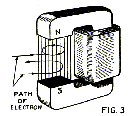
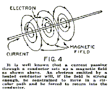
Another method, which has not found general application, depends on an electro-magnetic field on the electrons emitted by the filament. It is known that when an electron moves through a magnetic field, whose lines of force are at right angles to its direction of motion, the electron is constrained to move in a circular path (Fig. 3). In fact, if the field is made strong enough the electron may be forced to stay in the field and revolve in a circular orbit whose diameter is smaller the stronger the field. In this way if a magnetic field is applied transversely to the motion of the electrons in a vacuum tube the electrons may be deflected to such an extent as to prevent them from reaching the plate and to constrain them to return to the filament (Fig. 4).
In a small power tube a separate coil would have to supply the magnetic field, but in tubes of very large power employing heavy filament currents the magnetic field set up by this current is sufficient to deflect the electrons. It is of course necessary to make the magnetic field strong enough to overcome the electrostatic field between filament and plate.
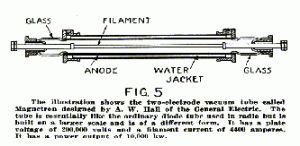
In the tube developed by Mr. Hall, which he calls “Magnetron” (Fig. 5), the filament is a straight wire coaxial with a cylindrical plate which forms the anode. The filament has a diameter of 2.0 cm. (.79 in.) while the diameter of the anode cylinder is 8.0 cm. (3.1 in.). A current of 4400 amperes is required to heat the filament, raising it to a temperature of 2500 degrees C. At this temperature the electron emission is intense enough to cause the flow of 170 amperes between the cylinder and the filament. However, these electrons do not reach the plate when the filament current is flowing, since they are deflected by the intense magnetic field set up by the current. This field prevents all electron flow even at a potential of 200,000 volts between cylinder and filament.
In other words the filament is heated by a heavy current giving rise to a large electronic emission, but this same current by the action of its magnetic field prevents any electrons from reaching the plate and thus no “plate” current flows, while the filament current is on. But if the filament current ceases after it has brought the filament to the proper temperature the magnetic field will collapse while the emission will continue, and therefore a current will flow between the anode and the filament. Thus, if the filament current is made alternating the plate current will flow every time the filament is zero.
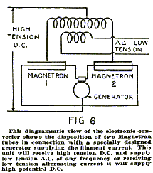
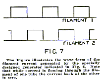
Fig. 6, represents a converter system comprising two magnetron tubes, one transformer with a central tap in the high tension winding and a generator of special design supplying a filament current of constant value but regularly interrupted. While this current flows through one tube the current in the other tube is zero, and visa versa. At any instant, therefore, the plate current flows through only one tube.
Now, suppose it is required to convert a high tension D.C. into a low tension 60 cycle A.C. The generator is adjusted to supply a current (see wave form Fig. 7) interrupted 60 times a second. Since the plate current flows only when the filament current is zero the current in the transformer will alternate at a frequency of 60 cycles per second.
This would be the action of the converter at the receiving end of the line. At the generating end it is required to convert A.C. into D.C. Here the generator supplying the filament current is driven synchronously with the A.C. generator so that the filament current is interrupted in synchronism with the alternator current. The current is thus reversed twice, first by the A.C. generator, and then by the converter system, and the resulting effect is a direct current in the high tension winding of the transformer.
The remarkable advantages of such system are manifest. Not only does it make long distance high potential transmission possible but offers an exceedingly flexible arrangement, the frequency of the converted current at the receiving end being entirely independent of the frequency of the A.C. generator. Such unit has been shown to be capable of converting 10,000 kw. At an efficiency of 96%. Furthermore the life of a magnetron is 60,000 hours, that is about seven years of continuos operation.


