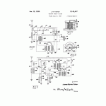
Fig. 6 shows a simple hook-up embodying the principles involved in the improved full-wave rectification of radiant energy waves in accordance with this invention. The principles there76 of will be explained so that they may be applied \ to more complex embodiments, by those conSversant with the art. A radio receiver, such as Sshown in Fig. 1 may readily have the full wave rectification applied thereto to produce increased efficiency with clear and stronger reception. 6 It is a further and Important feature of the Sfull wave rectification arrangement, that with a relatively few stages of amplification a current of high voltage may be generated from a relatively weak radiant wave and this voltage may be stepped down to a commercially usable voltage of practical amperage.
In Fig. 6 the receiver hook-up comprises the usual antenna 99 in a circuit of suitable design from the secondary 100 of which the signal E. M. F. passes over conductor 101 to a pair of grid leak condensers 102 and 103 which are connected thereto in parallel. The resistance of the grid leaks is of the order of three megohms and the condensers have a capacity of .00025 microfarad. The E. M. F. passing grid leak 103 follows conductor 104 to the screen 48 of a chemical rectifier 105 so that the rectification of the alternating E. M. F. takes place between member 48 and plate 49 and direct pulsating E. M. P. is taken off from plate 56 through conductor 106 over which it passes to one of a pair of magnetic pulsating generators 107 passing through the coil 108 and energizing the core 109 and returning to its negative or common ground through conductor S10. The magnetic pulsating generators in this embodiment are of the type shown in Fig. 2, the like parts other than the coils being referred to by like reference numerals. The permanent magnet 29 is oscillated by the pulsating E. M. F. in coil and core 108-109 and the movement of the pole causing a positive charge to be set up in the coils III and 112 which is taken off through conductor 113 connected across the top ends of said coils. The conductor 113 is connected with conductor 114 which leads to a regenerating coil 115 in the antenna circuit regenerating back to coil 100 for increasing oscillations therein. The opposite end of coil 115 connects by conductor 116 to a utilizing instrumentality, e. g., the head phones 117. The opposite sides of head phones I17 are connected by conductors 118 and 119 to the negative ends 120 of coils III and 112.
The E. M. F. passing grid leak condenser 102 follows conductor 121 to screen element 48 of chemical rectifier 122 effecting rectification between it and plate 49 of said chemical rectifier and putting forth D. C. pulsating E. M. F. through plate 56 of the chemical rectifier and conductor 123 which connects with the top of coil 124 in the second of the pair of magnetic pulsating generators indicated generally at 125. Coil 124 is grounded to conductor 126. The D. C. pulsating E. M. F. energizes coil 124 and its core effecting oscillation of the permanent magnet 29 in the manner previously described. This sets up the augmented pulsating D. C. E. M. F. the positive of which is taken from the top of electromagnet coils 127 and 128 passes through conductor 129 and thence over the conductor 114 through regenerating coil 115 and conductor 116 to the head phones 117 and thence over conductor 113 to the negative side of coils 127 and 128 through conductor 130.
The combination of the chemical rectifier and the magnetic pulsating generator as shown and described either in Fig. 1 or as shown in Fig. 2 and described herein may be suitably connected in circuit with an activating instrumentality which may be a suitably controlled power source or which may be as shown in Fig. 5, a magnetic type microphone (hereinafter described) in which latter case the transmitter requires no source of local energy for the transmission of tuned energy waves having their origin in the vibrations produced from sound.
Referring now specifically to Fig. 5, a magnetic microphone 131, by the vibration of sound waves striking the diaphragm 132 thereof, sets up an alternating current in the primary 133 of a microphone transformer 134 and thereby energizes transformer secondary 135. The operation of the microphone is later detailed. The induced energy in secondary 135 passes from the lower end through electromagnet coil 136 of a magnetic pulsating generator 131 and thence to common ground line 138. The other end of coil 135 connects to a grid circuit at 139 so that the secondary energy builds up in antenna coil 140. This energy also builds up in conductors 141 and 142.
Grid leak condenser 143 holds the energy at a substantial constant allowing it to pass to screen element 48 and plate 49 of a chemical rectifier 144. The energy in coil 136 causes rocking of permanent magnet 29 and this sets up an A. C.
E. M. F. in coils 145 and 146. These coils are connected at one end by conductor 141 with plate 49 and at the opposite end by conductor 148 to coil 149 which has regenerative relation to coil 140. The coil 149 connects through conductor 150 with plate 56 of the chemical rectifier 144 where rectification or intensification takes place and this energy is impressed upon the antenna 151. In this operation the chemical rectifier serves as a valve.
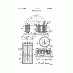
As shown in Figs. 7 and 8 the magnetic type microphone comprises a hollow wound coil 152 through the center of which extends a magnetic reed 153 pivoted as at 154 and having an arm 155 extending from one end, said arm carrying a diaphragm 132. A permanent magnet 158, preferably of horse shoe type, has its opposite ends 157 and 153 disposed closely in the path of the armature or reed 153 so that oscillation of said armature about its pivot may induce the weak E. M. F. in coil 152 which is transmitted to the primary 133 of transformer 134.
It will be understood that the transmitter just described may be enlarged in accordance with known practice to include push-pull transformer connections of the general character illustrated in Fig. 1 and that with an increased number of the magnetic pulsating generators in series, greatly increased signal strength may be imposed 5 upon the antenna.
It is also to be understood that the simplified form of magnetic pulsating generator illustrated in Fig. 1, may be utilized with somewhat decreased ultimate signal strength imposed upon the antenna. The operation and general formation of the hook-up will be readily appreciated by those conversant with the art by an inspection of Fig. 5 in conjunction with this statement.
Referring again to the preferred method of connecting the chemical rectifier (see Fig. 3) to an A. C. input source, the plate 14 would be connected to a conductor 159 and the screen member 15 would be connected to a conductor 160. The A. C. input would be connected to these connectors and the rectified current would be taken off through conductors 159 and 161, the latter conductor being connected to plate 13. Conductors 159 and ISO are bridged with a 1 microfarad fixed condenser and a three million ohm resistance.
y7 A similar arrangement is provided between conductors 160 and 161. The condensers are indicated at 162 and the resistances at 165.
The magnetic pulsating generator and the chemical rectifier of the invention are adaptable to use in television work, without any commercial current except that required by the customary photo-electric cell. A greatly clarified image is obtained in this case because, as previously explained, the magnetic pulsating generator and the chemical rectifier in conjunction effect a very material suppression of static or stray impulses. The magnetic pulsating generator and the chemical rectifier may be connected in a resistance coupled amplifier for this work.
The foregoing several disclosures will render clear to those skilled in the art, the manner in which the invention may be embodied in various devices that may employ radiant energy in any of its known applications. The embodiments illustrated and described are practical and are subject to modification and elaborations.
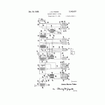
In Fig. 9 there is shown a pulsating generator with the parts identified as in Fig. 2. This is essentially a duplication of the permanent magnet 29 and output coils 20 and 23 operated from both ends of input coil 17 and its core IB. Under some conditions as much as 60% increase in output E. M. F. has been obtained compared with the output of the device of Fig. 2. Both of the magnets are simultaneously attracted to or repulsed by the ends of core 18 when coil 17 is energized. The movement of each magnet sets up useful voltages in its output coils 20 and 23 which feed to a common output circuit.
What is claimed is: 33 1. A magnetic pulsating generator comprising an input electromagnet coil, a laminated iron core therein, an output electromagnet coil, a laminated iron core for said output coil, a permanent magnet mounted for limited oscillation adjacent the ends of said cores, said permanent magnet having a pole disposed adjacent each of said cores, said cores being mounted in magnetically discontinuous relation whereby a relatively weak energization of said input coil may effect oscillation of the permanent magnet to induce an electromotive force in said output coil.
2. A magnetic pulsating generator comprising a core having an input coil thereon, a permanent magnet pivotally mounted with a pole thereof adjacent a pole of said core, a second core having an output coil thereon and having a pole thereof within the field of said permanent magnet, said output coil serving to build up an induced electromotive force upon oscillation of the permanent magnet by said input core and coil.
3. In a magnetic pulsating generator the combination of a U-shaped permanent magnet, a transverse integral bar portion on said magnet extending from one leg of said U-shaped portion toward the opposite leg of the U-shaped portion, said magnet having like poles at the junction of the leg and bar and at the free end of the bar, the end of the free leg of said magnet being of opposite polarity, insulating means mounting said magnet for oscillation, an input coil having a core terminating closely adjacent the junction of said leg and said bar portion of the magnet, a U-shaped laminated core having its ends re- 70 spectively, disposed closely adjacent the end of the bar portion and the free leg of said permanent magnet and a pair of oppositely wound electromagnet coils on the legs of said U-shaped core, said last mentioned coils being adapted to 7g be connected in parallel with a utilizing instrumentality.
4. A magnetic pulsating generator comprising an input electromagnet coil, a laminated iron core therein, a pair of output electromagnet coils, laminated iron cores therefor connected in magnetic continuity, one of said cores having a reduced and extended end, a permanent magnet mounted for limited oscillation adjacent the ends of all of said cores, said permanent magnet having a pole disposed adjacent each of the cores, and having the terminal poles thereof closely adjacent the reduced extended end of the core.
5. In a magnetic pulsating generator the combination of an input electromagnet coil, a core for said coil, a pair of U-shaped permanent magnets each having a bar portion extending from the end of one leg thereof towards the other leg, said magnets being mounted for oscillation and so disposed relative to the input core and coil as to dispose the junction of the leg and bar of one of said permanent magnets at each end of said core, pairs of oppositely wound electromagnet output coils disposed on each side of the input coil, each pair of output coils being disposed at one end closely adjacent the magnetic poles of the respective permanent magnets, each pair of output coils having cores in magnetic continunity and conductor means connecting all of the output electromagnet coils in parallel. JAMES MARION FISHER.
Click images to see bigger version
Download PDF version of Radiant Energy System by Fischer

