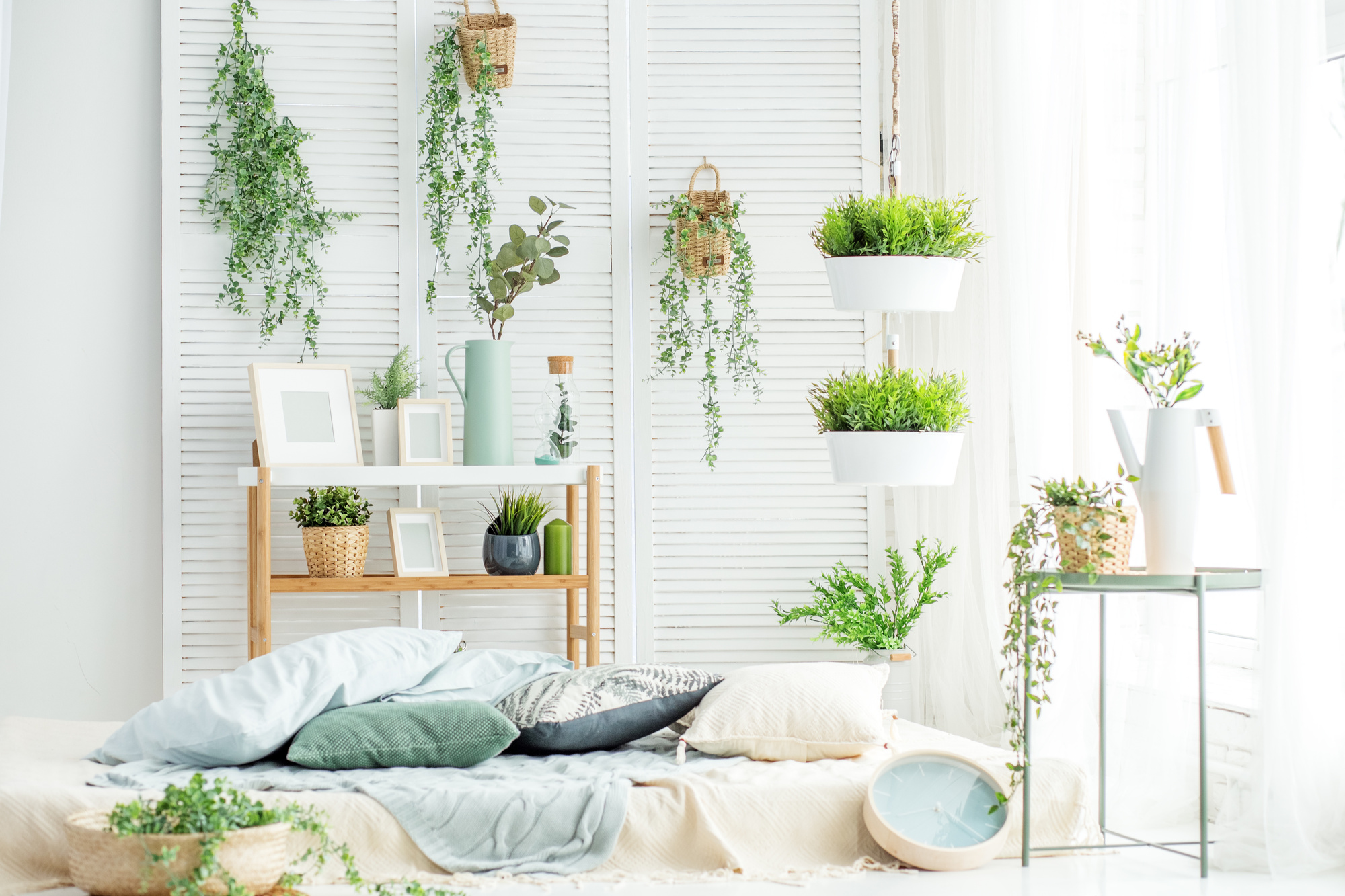
Perreault, Bruce.................November 16th, 1993
METHOD OF UTILIZING RADIANT ENERGY FOR THE GENERATION OF EFFICIENT ELECTRICAL ENERGY AND DEVICE
Inventor : Bruce A. Perreault, Mad River Road, Thornton, New Hampshire 03223
References Cited
U.S. Patent Documents
Number Name Date
685,957...........N. Tesla............Nov. 5, 1901
685,958...........N. Tesla............Nov. 5, 1901
1,540,998...........H. Plauson..........June 9, 1925
4,368,416...........James, deceased.....January 11, 1983
Other References
Primary Batteries (1891), Shelford Bidwell's Battery pg. 113
Direct Conversion of Energy (1964), by William R. Corliss pp. 28-29
Abstract
A method is disclosed for generating electrical energy, including a new and novel device. The device includes electropositive and electronegative electrodes. The electrodes are provided with electrical connections leading to the electrodes.
A sufficient amount of radiant energy applied to a reactive gas causes the gas to react ELECTROCHEMICALLY with the electropositive electrode. This causes an electrical current to flow between the electropositive and electronegative electrodes. An electronic circuit is used to absorb and convert the generated electric current.
BACKGROUND OF THE INVENTION
The present invention relates to a device for the conversion of radiant energy to electrical energy and more particularly, to the utilization of GAS IONIZATION to effect an electrochemical reaction. This device absorbs radiant energies emitted by natural or synthetic reactions, more particularly to a device and method that provides improved performance over prior art converters that convert radiant energies into electrical power.
There are devices that convert radiant energy to electrical current, with poor results.
U.S. Patent Nos. 685,957 and 685,958 issued both patents on November 5, 1901, utilizes air-borne ionized particles to charge an electrical capacitor. The accumulated ions jump a spark-gap and discharge through a load. One difficulty known to exist with this system is the low useable energy that develops.
U.S. Patent No. 1,540,998 issued June 9, 1925, calls for increased collecting surfaces of electrical capacitors, in an attempt to capture more energy. Yet another method converts high voltage and low current strength to voltages more suitable and of greater current. This system is impractical because of the required cumbersome balloons and collectors involved.
Atomic batteries generate electric currents by the disintegration of radioactive substances. William R. Corliss discusses the direct use of ionized particles expelled by radioisotopes in his report; Direct Conversion of Energy (1964) pp. 28-29. In this report high-velocity ionized negative particles emitted by strontium-90 creates a current of ionized particles.
The charge on the particles becomes neutralized by a metallic cylinder. The neutralized particles will find their way back to the strontium-90 becoming again ionized. This cycle repeats itself so long as the strontium-90 remains radioactive. The power generated by this method does not create USEABLE amounts of electrical energy.
Thermionic and thermoelectric energy conversion are discussed in U.S. Patent No. 4,368,416 - James, deceased January 11, 1983. One limitation known to exist with converters of this type is the relatively large heat source required to produce electrical power.
Nuclear reactors generate heat by burning UO2. This material is sensitive to X-ray energy. When the UO2 is exposed to X-ray energy it emits photoelectrons. The photoelectrons cause a chemical reaction. Present day nuclear reactors use a natural source of X-ray energy, called U235. This reaction produces heat. This heat boils water that produces steam.
The steam powers a turbine which in turn generates electricity. This type of energy generator requires complex building materials that make this method quite costly. Consumers have paid billions of dollars to build these power plants. Furthermore no one seems to know what to do with the waste products produced by these power plants. The U235 breaks up forming highly toxic radioisotopes.
Despite the prior art that exists in this technology, it is believed that previously there has not existed a small, compact electrical device capable of generating usable levels of power. It is the object of this invention to provide a method embodying an improved device to furnish efficient electrical power to a load.
The present invention removes limitations of past attempts to harness radiant energies. Toxic radioisotopes are not formed in the present invention. The primary object of the present invention is to provide a direct method for converting radiant energy to electrical energy, and a new and novel device for converting radiant energy with high efficiencies.
SUMMARY OF THE INVENTION
Thus in accordance with the present invention, there is provided a method of utilizing ionized particles for the generation of efficient electrical energy.
In the present invention, new and novel improvements are apparent. The need for an enormous collector surface no longer exists. Transistors can now replace the outdated spark gap and or high vacuum transmission tubes. The present invention efficiently converts ionizing energy to voltages suitable for practical usage.
A source of X-ray energy is provided by the present invention. This source can be artificially generated and will not produce toxic radioisotopes.
Converted energy in the present invention may be directly available for driving motors, lighting, production of heat and used in electrochemistry.
The method of the invention includes, means for exposing a REACTIVE GAS, such as CHLORINE to a source of ionizing energy.
Other objects and advantages of the present invention will become apparent from the following description of the preferred embodiment of the present invention, with references to the attached drawings, in which:
Fig. 1 is a block diagram of the present invention;
Fig. 2 is a diagram showing the present invention being exposed to a source of ionizing energy of extreme voltage and of short duration.
DETAILED DESCRIPTION OF THE PREFERRED EMBODIMENTS
Thus in accordance with the present invention, there is provided a radiant energy converter comprising a first metallic electrode made of ZINC METAL and a second metallic electrode made of IRON SULFIDE nested parallel to the first electrode.
A number of electrode couples may be used and still not depart from the spirit of this invention. The inter-electrode spacing contains the reactive gas CHLORINE. A number of gasses MAY BE USED and still not depart from the spirit of this invention. Means are also provided, at the end of the electrodes, to provide external electrical leads from the electrodes to a load circuit.
The method to generate electrical energy also includes, with a device just described, means for exposing the internal reactive gas to a radiant energy source of sufficient strength.
The conversion of radiant energy to useful electrical energy is apparent. The small solid-state components of this apparatus make it a practical compact unit. An electronic circuit effects energy absorption.
The electronegative electrode may contain oxygen gas in the form of a solid. Manganese dioxide may be used for this purpose. The electropositive electrode may contain hydrogen gas in the form of a solid. Lithium hydride may be used for this purpose.
The gasses react when the inter-electrode spacing of these electrodes is subjected to radiant energy pulses. The gasses become SUPER CONDUCTIVE. This causes the oxygen and hydrogen gasses to react chemically with minute energy loss. Chemical energy is now converted to electrical energy with extreme efficiency. Furthermore, an electrical transformer can be utilized to transform this electromotive energy to a usable voltage.
Referring now to FIG. 1 of the drawings,
(1) consists of a gas tight vessel. Provision is made for an inlet tube (2) to introduce chlorine gas (3). Provision is made for iron sulfide electrode (4) and zinc electrode (5).
ANY NUMBER of electrode couples, or gas combinations may be utilized and still not depart from the spirit of this invention. A source of ionization (6) is provided.
The chlorine gas (3) must become ionized in order for it to bombard the electrode (5). When the chlorine gas (3) is ionized it becomes a conductor, its conductivity is a measure of its ionization.
There are a number of ways to ionize the chlorine gas (3). X-ray energies emitted from the sun will ionize the chlorine gas (3). Radioactive materials will ionize the chlorine gas (3). Pulsating high-voltage produced by an electrical transformer will ionize the chlorine gas (3).
Any number of ionizing sources may be utilized and still not depart from the spirit of my invention. I stake my claim to the method of power generation.
If an electronic ionizing source (6) is used, once started, the energy produced by said invention will keep the electronic circuit energized.
Initially the electronic circuit must be PRIMED by an outside power source (7). When said invention begins generating electrical energy the external source (7) IS NO LONGER NEEDED. A small rechargeable battery may be used as the external source (7). Said invention will keep the external source (7) fully charged.
Greater amounts of energy can be stored in a compact manner than any previously known electrochemical system. Furthermore, if radiant energy is used as the ionizing source its energy is converted into electrical power.
The voltage from said invention is very stable. The output can be varied from a non-pulsating, direct current, to a high frequency pulsating output. The output pulsation rate is varied by the rate in which the electronic ionizing source (6) pulsates.
The pulsation rate of the ionizing source (6) is determined by its circuit characteristics. These characteristics are well known in the engineering field. Any number of known electronic circuits may be utilized for the electronic ionizing source (6) and still not depart from the spirit of said invention. If the ionizing source comes from radiant energy the pulse rate is a factor in the decay rate.
Nu
Energy Research Laboratories
Nu Energy Research Laboratories, P. O. Box 22, Rumney, New Hampshire 03266-0022 USA
Copyright © 2004, All Rights Reserved