This article deals with a device known as the Markovich which was developed in the late 1970’s by John Markovich. There has since then been a few rumors that the device was a fraud and batteries were used, however in view of some of the amperages that were involved and the running times, it would appear difficult to have fraudulently created the results with the simple torch batteries that are supposed to have been used in the fraud. The article is in some aspects a bit vague and without enough actual reference to the original sources of some of the information, however it is interesting since the discussion of space energy that can be related to present studies on T.H. Moray’s radiant energy. The author of this article is unknown.
The device in question is one of a number of energy transducers that converts extremely high frequency energy to a form comparable to alternating or direct current electricity. The process involves in all cases, the utilizing of the instrument as a specially designed resonating cavity. This cavity can be composed of either a number of crystals, a series of coils, or a combination of the above. To understand how the unit operates, it is first necessary to briefly describe the nature of this energy source.
Research and experimentation have established that this energy is one that pervades the known universe and is constantly flowing through the Earth itself. It has been found to be quite dense, with enough power to light an American city of around 50,000 persons for a year. Because of its origins and immense power potential, this energy has been called “vacuum,” “cosmic,” “radiant,” or “zero-point” energy. Dr. Nikola Tesla, the discoverer of the electric age, may have used this energy to create his most fantastic invention-the “Magnifying Transmitter.”
At the beginning of this century, Tesla was able to send electrical energy through the earth without the use of wires. In a test transmission, he sent electricity to a receiver located twenty six miles away where a bank of 200 fifty watt light bulbs lit for as long as the transmitter operated. This demonstration convinced Tesla that he had learned the principles of operating the Earth as a gigantic resonating cavity. This resonating cavity had the ability to conduct not only electricity, but also radio waves and any other type of electromagnetic wave. However, the key part was the ability of the transmitter to magnify electromagnetic waves. Also, the device had the ability to transmit this energy at a frequency comparable to the Schuman cycle (6 to 13 hertz). This fact indicated that Tesla had stumbled onto a new form of energy directly convertible into electricity. Evidence of this discovery can be seen in two actions taken by Tesla after the success of the Colorado Springs Experiments. In July 1902, he wrote a letter to Robert Underwood Johnson in which there was mentioned a discovery of a new unknown energy that could be used to create “fuel-less motors.” At the same time, Tesla was demonstrating these devices to other friends and refusing to apply for U.S. patents.
Recently researchers have discovered a number of interesting facts about Tesla’s energy. First the energy traveled through the universe as a spiraling stationary wave or corkscrew. Second the energy can be conducted by electrical instruments (wires, etc.) composed of metals that are also excellent conductors of electricity (gold, silver, copper, etc). Strangely, those conductors that have no known natural magnetic property such as aluminum can not be used to collect these energies, but only to disperse them. Finally the energy in its corkscrew fashion carried itself around the outside of a wire and not through it as was the case with conventional electricity. Hence, it will be necessary to construct motors that are wound slightly differently in order to make the best use of this energy source. However it will be possible to inter-phase this energy into the modern electrical world and gradually “phase in” the new system.
It is one thing to acknowledge the presence of this strange form of energy, but quite another to construct a successful transducer device. To do so a potential inventor must realize that one should design a device that will have a number of interesting properties. First the instrument must be constructed of materials that can collect the energy, i.e., conductive metals such as copper, silver, etc. Second, the unit must be able to gradually step down the energy. This process can be accomplished by a series of tightly wound coils or else a specially faceted quartz crystal that is connected in series to a number of tightly wound coils. It is the purpose of the first set of spiral coils or of the crystal to act as the source of control for the “electrical energy” in the circuit. The crystal or spiral coil receives this “energy” from a “collector” and converter coils that are attached to it. For the system to operate efficiently, the collector and converter coils must be of a similar shape as the coils that directly surround the crystal or else a harmonic ratio of the crystal and its coils. By putting the energy through enough turns of wire and constructing a properly faceted crystal, one is able to drop the energy to a frequency that can be inter-phased with electrical circuitry. Such a device will only encounter two potential problems. First, there is the great amount of radiant energy that can be given off by an improperly tuned coil. This problem can be overcome by the use of a proper amount of windings and the substitution of materials that are more conductive than those used in previous models. Finally, one must overcome the problem of lower amperages in crystal units. This problem can be solved by the use of a system of specially constructed grounds and the use of smaller crystals in the circuitry between the crystal control system and the collection and conversion system. In this way, improper balances in the device can be overcome in the development of this new system.
As we have seen, there exists a number of ways to successfully convert space energy into electrical energy. This largely unknown energy can be used to perform all the important tasks that can be presently accomplished by electricity. That is, the energy can be utilized as a communications system, power system, or transportation system.
Space Energy Power System
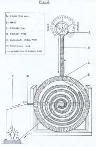
To convert this energy into electricity, it is essential that a component be provided that can both collect and begin the conversion of the energy found near the surface of the planet. This part must be able to receive, store, and conduct the energy to the unit that actually rectifies this energy into dc electricity. Due to its corkscrew motion, high frequency and other near electrical properties, it has been found that this energy can best be collected by a hollow ball whose outside diameter is one sixth of the height of the rectifying unit. Furthermore, this ball should be constructed of a fairly thin conductive metal (#11 gauge sheet metal or less) In our case we chose a ball made of copper (Figure 2) In operation, the energy will first collect around the outside of the ball. This energy will then enter the inside of the ball and collect on the inner surface in a fashion similar to an electrostatic charge. Hence, the ball has received the energy and due to its conductivity and shape stored the energy as a “charge” on its inner plate. To get this energy to the rectifier, it is essential to devise a means to send the collected swirl of energy to the induction rod. This act is accomplished by employing an electrical property of “space energy.” The top 5% of the copper rod is formed into a needle shaped tip that permits the energy’s “charge” to flow down it like a standard electrostatic charge would by “jumping the gap” to an electrode (tip) in order to complete the fastest possible return to ground. Wound around the “induction rod” is #26 AWG seven stranded hook up wire, the wire is loosely wound over the first six inches of the rod and then tightly wound around the rest of the rod. Finally, the use of #14 AWG household wire is employed in a coil wound in the direction opposite of the coil on the “induction” rod. This coil is affixed on the top to the ball and on the bottom to the working electrical circuit. This entire unit is encase in 1¼ -inch copper tubing.
Conversion of “space energy” resembles in many ways the electromagnetic induction principle first discovered by Henry and Faraday in the last century. As noted previously, this energy has near electromagnetic properties. These properties include the presence of two quasi-vectors, a quasi-electrical (L) field and a quasi-magnetic (H) field. This second or quasi-magnetic field differs from the traditional concept of magnetism by having its flux (lines of force) bend inward instead of magnetism’s outward direction. To induce electricity, it is necessary that two dissimilar energy flows be set up. The first is through the copper rod and the second through the coil wound around the rod. Apparently, this difference in distance and speed (wire resistance) off flow creates the conditions similar to the moving of an iron core through a magnetic field, that is, an electrical current is induced. This phenomenon is due to the quasi-magnetism present in both the copper rod and coil (Iron nails will stick to the outer copper tube). Thus, a corollary of the Faraday Law of Electromagnetic induction is clearly found in the induction unit. Further proof of this inductive effect comes from the fact that the counter-coil seems to act much in the manner of the secondary coil of a transformer (amplifies voltage).
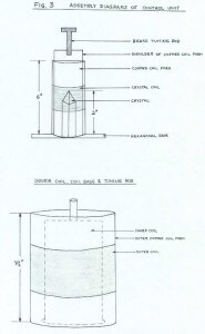
Once the energy leaves the induction unit, it enters the “control unit.” This unit is composed of a central piezoelectric quartz crystal that is mounted on a tuning (moveable) base attached to the bottom of a hexagonal hardwood resonating chamber. This instrument acts as the split or frequency tuning capacitor. That is, the “control unit” accomplishes the final tuning of the energy so that the maximum amount of energy can be converted into electricity. This circuit begins at the top of the box and passes to a flat spiral coil placed beneath the top of the box. This coil is glued to the copper sheathing that comprises the actual resonating chamber. This “roof coil” starts the process by directing the energy to the crystals upper facets into the working circuit. Next, the energy travels to the inner counter-wound vertical coil called “the crystal coils” through the use of a “slip ring.” Here, it is exposed to the energy of the sides or long facets of the crystal. Finally, the energy travels through the main coils, a counter-wound vertical coil glued to the bottom sheathed resonance chamber. By this time, the resonance induced by tuning (turning) the crystal has increased the efficiency of the conversion process. This phenomenon is due to two factors. First, the crystal has the ability to control the amount of voltage in the circuit. This effect is found in standard electrical theory in the use of split capacitors to tune circuits and in this way increase the “Q” efficiency of an induction coil (commonly employed in microwave and radio circuits). Secondly, the unit has the property to increase or decrease the amount of resistance in a given circuit. This was demonstrated by the boxes ability to burn out a 70Vdc, 2 amp step-down transformer. By the use of these properties the control unit is able to transform the energy from the conduction unit into a more stable electrical form.
To sum up let us quickly review the entire conversion process. First, the energy jumps to the tip of the inductor rod and is conducted to the opposite end of the rod. Simultaneously, this energy flows through the tightly wound induction coil. The difference in rate and distance allows the rod and coil to induce an electrical current. Finally, the energy is sent to the control unit to stabilize the converted energy. The main working circuit for the system consists of a primary tube (core and coil assembly labeled C and D in diagram 2) and the secondary spiral tube (core and coil assembly labeled E in diagram 2) In this fashion the device is able to covert “space energy” into a useable form of DC electricity.
The images below reproduce the hand drawn diagrams that were included in the original article.


According to reports the device is supposed to have worked, with maximum voltage of around 180V and 3 amps. Strangely both a DC and an AC component were found in the output. There were some pretty high powered witnesses to these experiments including scientists and technicians.


